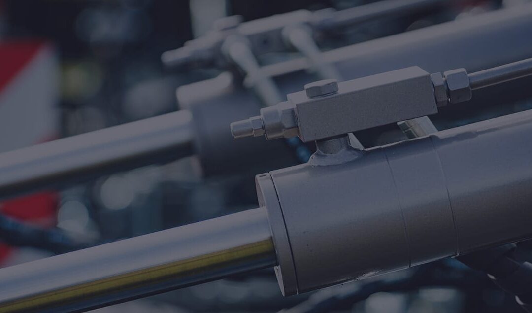
Fundamentals of Hydraulic Systems in Truck-Mounted Applications
Hydraulic Repair Near Me Hydraulic systems in truck-mounted applications share core components and operational principles with all hydraulic systems. These systems consist of a power source, reservoir, pump, directional control valve, and actuators that manage and move fluids to perform tasks. Starting with mechanical power from a rotating shaft, this power is transformed into hydraulic power via the pump. It is then directed through a valve to a cylinder or motor and finally reconverted into mechanical power. This transformation allows for precise force application through fluid power.
Hydraulic Repair Near Me Hydraulic systems operate based on their flow and pressure requirements. The flow rate, indicated in gallons per minute (GPM), determines the speed of hydraulic cylinder extension or motor rotation, generated by the pump. Pressure, measured in pounds per square inch (PSI), dictates the exerted force. The interplay of flow and pressure defines the system’s operational horsepower (HP), calculated by the formula: HP = GPM × PSI ÷ 1,714.
The basis of hydraulic principal is based on Pascal’s Rule. It states that pressure applied to a confined fluid is evenly, instantly, and completely transmitted in all container directions. This principle is vital in hydraulic systems, as oil (being almost non-compressible) instantly transmits any applied force.
Understanding the difference between flow and pressure is crucial for troubleshooting: flow impacts actuator speed, while pressure affects system force. Problems in lifting a load typically indicate pressure issues, whereas slow performance suggests flow problems.
Truck-mounted Hydraulic Repair Near Me hydraulic systems also abide by additional principles, such as Boyle’s Law, Charles’ Law, and Henry-Dalton’s Law, which influence air behavior and can lead to issues like cavitation and aeration. Open-center systems maintain continuous flow and intermittent pressure, directing flow through a valve to the tank when inactive. Closed-center systems, conversely, keep continuous pressure with intermittent flow, producing just enough flow to maintain standby pressure at the valve.
Understanding these principles and the interplay of different components and pressures is key to effectively operating and troubleshooting truck-mounted hydraulic systems.
The Driving Force Behind Hydraulic Systems
The prime mover is the main source of mechanical power for a hydraulic system. This power is usually transferred through a power take-off (PTO), belts linked to the crankshaft pulley, or directly via a tubular driveshaft assembly. For systems requiring more power, an auxiliary or pony engine might be employed. Power Take-Offs (PTOs)
Initially, PTOs were simple, single gear models engaging with a transmission gear to rotate the output shaft. These are primarily seen in smaller vehicles like single axle dump trucks and agricultural equipment. However, single gear PTOs are largely outdated now.
Today’s PTOs, often double or triple gear models, offer greater versatility and are widely used in various vehicles, including dump trucks, refuse collectors, and cranes. These PTOs can be activated via cable, air, electric solenoid, or mechanical levers, and they accommodate a range of output shafts and mounting flanges, facilitating direct coupling with hydraulic pumps from major manufacturers. Changing the internal gear ratio can adjust PTO output shaft speeds. Clutch shift PTOs, a newer design, engage with friction disks and are commonly found in garbage trucks and emergency vehicles.
Hydraulic Repair Near Me Engine Crankshaft Driven Systems
Some vehicles, like refuse and snow control trucks, use a front-mounted hydraulic pump driven by a driveshaft from the engine’s harmonic balancer. It requires modifications like raising the radiator, extending the front frame rails, and creating a pump mounting bracket.
Drivelines in these systems must be balanced and capable of handling high torque loads, with specific considerations for driveshaft angularity and alignment to avoid vibration and pump damage.
Hydraulic Repair Near Me Belt-Driven Pumps
Also known as clutch pumps, belt-driven pumps are common in vehicles like wreckers and bucket trucks. They serve as alternatives to PTO systems in vehicles without PTO openings or where access is blocked. However, the horsepower capacity of the engine belts limits their application. Most systems use two v-belts or a poly-v type belt for driving the pump, but space limitations often restrict the use of large displacement pumps in these setups. Serpentine belt drives can deliver horsepower comparable to two v-belts.
Despite challenges posed by changing truck designs and crowded engine compartments, clutch pumps remain a favored choice for hydraulic systems requiring up to 15 GPM flow rates.Choosing the Right Hydraulic Hose for Your Application
When selecting a hydraulic hose, it’s essential to consider several key factors to ensure it fits your specific needs. Here’s what to look for:
Hose Layline Information
The Hydraulic Repair Near Me hose layline typically includes the maximum working pressure (WP) and other vital details like the inside diameter, manufacturer and model name, and size. This information is essential whether you’re replacing an existing hose or constructing a new hydraulic system.
Considerations for Hose Selection
- Pressure Rating: Choose a hose with a maximum working pressure rating at or above your hydraulic system’s normal maximum pressure. The hose should be able to handle momentary pressure surges without exceeding this rating.
Selecting the Right Material for Your Hydraulic Hose
When choosing a hydraulic hose, whether for replacing an existing one or for a new system, it’s crucial to consider the appropriate material based on your specific needs. The hose’s pressure rating, diameter, length, and material properties should align with your application’s requirements. Here’s what to consider in terms of materials:
Thermoplastic hydraulic hoses are known for their tight minimum bend radius, making them highly resistant to kinking. Generally, these hoses are lighter compared to their rubber counterparts. The inner tube in thermoplastic hoses is usually made of copolyester or nylon and is often reinforced with a synthetic fiber, such as braided or spiral-wrapped synthetic fiber, rather than steel. This synthetic reinforcement is particularly crucial for electrically non-conductive hoses (often with an orange cover) used in aerial lifts.
Moreover, the outer cover of Hydraulic Repair Near Me thermoplastic hoses is typically made of polyurethane. This choice of material aides to an older shelf lift when compared to hoses made of rubber. In environments with low temperature, these thermoplastic hoses display a higher strength against UV rays and chemicals, which make them a tough and versatile option for many applications of hydraulics.